3.3 - Temperature Glide Bubble Point and Dew Point
Technical source review date: August 7, 2026
Primary technical basis: Current project Module 3 outline, HVAC licensing study guidance, and ASHRAE-based refrigerant property tables in NCEES PE Mechanical reference data
Course role: Explains how zeotropic refrigerant blends use bubble-point and dew-point saturation temperatures and how those values affect pressure-temperature interpretation, superheat, subcooling, charging, and leak-related service decisions
Learning Objectives
After completing this section, a student should be able to:
- Define temperature glide, bubble point, and dew point for a zeotropic refrigerant blend.
- Explain what occurs between the bubble point and dew point during evaporation and condensation.
- Select the correct bubble-point or dew-point value from a pressure-temperature reference for a technician-level calculation.
- Explain why dew-point temperature is normally used for superheat and bubble-point temperature is normally used for subcooling.
- Relate temperature glide to blend charging and possible fractionation after refrigerant loss.
- Avoid common overgeneralizations about glide, fractionation, and pressure-temperature identification.
Introduction
For a pure refrigerant, one saturation pressure corresponds to one saturation temperature.
A zeotropic refrigerant blend is different.
At a given pressure, a zeotropic blend can begin phase change at one temperature and finish phase change at another. The temperature interval between those two saturation limits is called temperature glide.
The two endpoints are:
- Bubble point — the saturated-liquid limit.
- Dew point — the saturated-vapor limit.
For the zeotropic blends discussed in this module:
Bubble-point temperature
< two-phase temperature range <
Dew-point temperature
at the same pressure.
This distinction is important because a pressure-temperature chart for a zeotropic blend may provide two saturation temperatures for the same pressure.
A technician must therefore know whether the situation involves:
- Saturated liquid.
- Saturated vapor.
- Superheat.
- Subcooling.
- Evaporation.
- Condensation.
Using the wrong saturation column can produce an incorrect temperature difference even when the pressure reading itself is correct.
Temperature glide is the difference between the dew point and bubble point of a refrigerant at a given pressure, and property references list separate bubble and dew temperatures for blended refrigerants such as R-410A.
Key Concepts
1. Temperature Glide
Temperature glide is the change in saturation temperature that occurs while a zeotropic blend changes phase at approximately constant pressure.
At technician level:
where:
- = dew-point temperature at the selected pressure.
- = bubble-point temperature at the same pressure.
For a typical zeotropic blend:
Tbubble < Tdew
Therefore, glide is a positive temperature difference.
2. Glide Occurs Through the Two-Phase Region
During evaporation at approximately constant pressure:
Saturated liquid
at bubble point
→
liquid-vapor mixture
→
saturated vapor
at dew point
The blend temperature rises through the two-phase region.
During condensation at approximately constant pressure:
Saturated vapor
at dew point
→
vapor-liquid mixture
→
saturated liquid
at bubble point
The blend temperature falls through the two-phase region.
This behavior differs from the simplified pure-refrigerant model in which saturation temperature remains essentially constant during phase change at constant pressure.
3. Glide Magnitude Depends on the Blend
Not every 400-series blend has the same glide.
Some zeotropic blends have:
- Noticeable glide.
- Moderate glide.
- Very small glide.
A zeotropic blend with very small glide is often called near-azeotropic.
As established in Section 3.2:
A near-azeotropic refrigerant is still a zeotropic blend.
R-410A is a common example of a 400-series blend with very small bubble-to-dew temperature difference in published property tables. These tables still list separate bubble and dew temperatures, confirming that the two saturation limits exist even though the difference is small.
Bubble Point
1. Definition
For a zeotropic refrigerant blend at a specified pressure, the bubble point is the saturated-liquid temperature.
When saturated liquid is heated at that pressure, the bubble point is the condition at which the first vapor begins to form.
A useful technician description is:
Bubble point = liquid saturation temperature.
2. Heating Through the Bubble Point
Consider a zeotropic blend that begins as subcooled liquid.
As heat is added at approximately constant pressure:
Subcooled liquid
→
bubble point
→
first vapor begins to form
→
two-phase evaporation continues
Once the blend enters the two-phase region, the temperature does not remain at one fixed value. It moves from the bubble-point temperature toward the dew-point temperature.
3. Cooling Toward the Bubble Point
During condensation, the bubble point is the end of condensation.
As heat is removed:
Saturated vapor at dew point
→
two-phase condensation
→
last vapor condenses
→
saturated liquid at bubble point
Further cooling below the bubble-point temperature produces subcooled liquid.
4. Bubble Point and Subcooling
For a zeotropic blend, bubble-point temperature is normally the saturation reference used for subcooling.
Conceptually:
when both values correspond to the same pressure location.
The reason is physical:
- Bubble point represents the saturated-liquid boundary.
- Subcooling describes how far the actual liquid temperature is below that saturated-liquid temperature.
Detailed field measurement procedures are developed in Module 4.
Dew Point
1. Definition
For a zeotropic refrigerant blend at a specified pressure, the dew point is the saturated-vapor temperature.
When saturated vapor is cooled at that pressure, the dew point is the condition at which the first liquid begins to form.
A useful technician description is:
Dew point = vapor saturation temperature.
2. Heating Toward the Dew Point
During evaporation, the dew point is the end of evaporation.
As heat is added:
Saturated liquid at bubble point
→
two-phase evaporation
→
last liquid evaporates
→
saturated vapor at dew point
Further heating above the dew-point temperature produces superheated vapor.
3. Cooling Through the Dew Point
Consider superheated blend vapor.
As heat is removed at approximately constant pressure:
Superheated vapor
→
dew point
→
first liquid begins to form
→
two-phase condensation continues
The temperature then falls through the glide range toward the bubble point.
4. Dew Point and Superheat
For a zeotropic blend, dew-point temperature is normally the saturation reference used for superheat.
Conceptually:
when both values correspond to the same pressure location.
The reason is physical:
- Dew point represents the saturated-vapor boundary.
- Superheat describes how far the actual vapor temperature is above that saturated-vapor temperature.
Bubble Point and Dew Point Compared
| Item | Bubble Point | Dew Point |
|---|---|---|
| Saturation boundary | Saturated liquid | Saturated vapor |
| Heating interpretation | First vapor begins to form | Last liquid finishes evaporating |
| Cooling interpretation | Last vapor finishes condensing | First liquid begins to form |
| P-T chart column | Liquid / bubble | Vapor / dew |
| Primary technician calculation | Subcooling | Superheat |
| Relative temperature for a typical zeotrope at same pressure | Lower | Higher |
Memory Aid
Bubble → liquid side
Dew → vapor side
Another useful reasoning sequence is:
Superheat asks about vapor
→ use dew

Subcooling asks about liquid
→ use bubble
Understanding the phase boundary is more reliable than memorizing the words alone.
Pressure-Temperature Chart Interpretation for Blends
1. Why a Blend P-T Chart Can Have Two Temperatures
A pressure-temperature reference for a zeotropic blend can include:
| Pressure | Bubble Temperature | Dew Temperature |
|---|---|---|
| Same pressure | Saturated-liquid value | Saturated-vapor value |
The two temperatures define the approximate phase-change range at that pressure.
Refrigerant blend property data are commonly labeled as “Properties of Liquid on Bubble Line and Vapor on Dew Line” and provide separate bubble and dew temperatures.
2. Step-by-Step Chart Selection
When using a blend P-T reference:
- Identify the refrigerant.
- Identify the measured pressure.
- Confirm whether the table uses gauge pressure or absolute pressure.
- Determine whether the calculation concerns liquid or vapor.
- Select the correct saturation column.
- Compare the saturation temperature with the measured line temperature.
For common technician calculations:
Superheat → dew-point column
Subcooling → bubble-point column
3. Superheat Example Without a Full P-T Table
Suppose the technician has already obtained the correct dew-point saturation temperature from an approved P-T reference.
If:
Dew-point saturation temperature = 45°F
Measured vapor-line temperature = 57°F
then:
The important Section 3.3 concept is not the arithmetic. It is choosing dew point because the calculation concerns vapor.
4. Subcooling Example Without a Full P-T Table
Suppose the correct bubble-point saturation temperature is:
Bubble-point saturation temperature = 100°F
Measured liquid-line temperature = 88°F
then:
The important concept is choosing bubble point because the calculation concerns liquid.
5. Do Not Average Bubble and Dew Automatically
Some teaching materials discuss midpoint or average saturation temperatures for particular engineering analyses.
That does not create a universal service rule.
For the technician-level calculations emphasized here:
- Use dew point for superheat.
- Use bubble point for subcooling.
- Use the equipment or refrigerant manufacturer’s instructions when a procedure specifies a different or more detailed method.
Do not automatically average the bubble and dew values unless the specific procedure requires it.
Evaporation Through a Temperature Glide
1. Evaporator Sequence
At approximately constant evaporating pressure:
Bubble point
↓
evaporation begins
↓
two-phase mixture warms through the glide
↓
dew point
↓
evaporation is complete
↓
superheat can begin
Therefore, the blend can be absorbing latent heat while its temperature changes.
This is one reason the phrase:
“Refrigerant boils at one constant temperature”
must be qualified when discussing zeotropic blends.
2. Heat Exchanger Temperature Difference
Because refrigerant temperature changes during phase change, the temperature difference between:
- Refrigerant, and
- Air, water, brine, or another heat-transfer fluid
can vary along the heat exchanger.
This can influence system design and performance.
For EPA 608 preparation, the important point is simply:
Temperature glide means the refrigerant does not remain at one saturation temperature throughout the two-phase process.
Detailed heat-exchanger design consequences are beyond the scope of this section.
Condensation Through a Temperature Glide
1. Condenser Sequence
At approximately constant condensing pressure:
Dew point
↓
condensation begins
↓
two-phase mixture cools through the glide
↓
bubble point
↓
condensation is complete
↓
subcooling can begin
This is the reverse of evaporation.
2. Correct Endpoints
During condensation:
- Dew point marks the saturated-vapor side.
- Bubble point marks the saturated-liquid side.
Do not reverse these endpoints.
Charging Implications
1. Glide and Composition Are Related Blend Concepts
Temperature glide occurs because the components of a zeotropic blend do not have identical volatility.
That same difference in volatility can cause the liquid and vapor phases to have different compositions.
Therefore, temperature glide and fractionation are related, but they are not the same concept.
2. Charging Reminder
As established in Section 3.2:
Zeotropic refrigerants are normally withdrawn from the supply cylinder as liquid.
The purpose is to preserve the specified blend composition as closely as possible.
Temperature glide does not change that handling rule.
3. Liquid Withdrawal Versus Compressor Protection
Do not confuse:
Withdraw zeotropic blend from cylinder as liquid
with:
Allow liquid refrigerant to enter a running compressor
The first is a blend-composition rule.
The second is a compressor-protection issue.
If refrigerant is introduced through the low side of an operating system, use the manufacturer’s approved method to meter or vaporize it safely.
Leak and Fractionation Implications
1. A Leak Can Change Blend Composition
Because vapor and liquid can have different component proportions, preferential loss of one phase can alter the remaining blend composition.
This is fractionation.
A leak involving a zeotropic blend can therefore affect:
- Composition.
- Pressure-temperature relationship.
- Temperature glide.
- System performance.
2. Do Not Assume Every Leak Produces the Same Result
A common overgeneralization is:
“Any leak means the entire blend is ruined.”
That statement is too broad.
The actual effect depends on:
- Blend characteristics.
- Leak size.
- Leak location.
- Whether refrigerant escapes primarily as vapor, liquid, or a changing mixture.
- System operating or shutdown condition.
- Amount of refrigerant lost.
The project sources support treating fractionation as a blend-handling concern, but they do not support one universal percentage of leakage after which every charge must be discarded.
Therefore:
- Do not invent a fixed leak threshold for blend replacement.
- Follow the refrigerant and equipment manufacturer’s service instructions.
- If refrigerant identity or composition is uncertain, do not assume the remaining charge still matches the original formulation.
3. Recovery Does Not Reverse Previous Fractionation
Recovering the remaining charge:
- Captures the refrigerant.
- Prevents additional intentional release.
- Helps keep the recovered refrigerant together as a blend.
Recovery does not automatically restore the blend to its original factory composition if fractionation already occurred.
Avoiding Overgeneralization
1. Not Every 400-Series Blend Has Large Glide
The 400 series identifies zeotropic blends.
It does not mean:
Every 400-series refrigerant has a large glide.
Some 400-series blends are near-azeotropic and have very small glide.
2. Small Glide Is Not Zero Glide
A blend can have bubble and dew values that are very close together.
That does not make it a pure refrigerant.
It also does not convert the refrigerant into a 500-series azeotrope.
3. Bubble and Dew Values Are Refrigerant Specific
Do not use:
- R-407C bubble/dew data for R-410A.
- R-410A data for R-454B.
- One manufacturer’s chart for a different refrigerant designation.
The refrigerant must be correctly identified first.
4. Pressure Alone Does Not Identify an Unknown Refrigerant
A pressure reading can be compared with expected P-T behavior, but pressure alone is not conclusive identification.
Factors such as:
- Actual refrigerant temperature.
- Noncondensables.
- Mixed refrigerants.
- Incorrect charge.
- Recent operation.
- Contamination.
can affect interpretation.
Refrigerant identification is developed in Section 3.4.
5. Do Not Use the Wrong Side of the Glide
For a zeotropic blend:
Bubble = liquid saturation boundary
Dew = vapor saturation boundary
Using bubble temperature for superheat or dew temperature for subcooling can create a systematic calculation error approximately related to the blend’s glide.
The larger the glide, the more important correct endpoint selection becomes.
Technical Details
1. Temperature Glide Equation
At a selected pressure:
This definition is consistent with standard technician guidance that describes temperature glide as the difference between dew point and bubble point at a given pressure.
2. Bubble and Dew Are Saturation Limits
For a zeotropic blend at a selected pressure:
Below Tbubble
→ subcooled liquid region

Tbubble
→ saturated-liquid boundary

Between Tbubble and Tdew
→ two-phase region

Tdew
→ saturated-vapor boundary

Above Tdew
→ superheated vapor region
This is a simplified technician-level interpretation at the selected pressure.
3. Phase Change Is Reversible
Heating:
Bubble → two phase → Dew
Evaporation
Cooling:
Dew → two phase → Bubble
Condensation
The physics is reversible even though the direction of heat transfer changes.
4. Published P-T Data Must Define Its Pressure Basis
A chart or table must be read using the pressure units provided by that source.
Possible pressure references include:
- psig.
- psia.
- bar gauge.
- bar absolute.
- kPa gauge.
- kPa absolute.
Do not compare a gauge-pressure measurement directly with an absolute-pressure table without the required conversion.
5. Use Verified Data for Numerical Problems
The project outline requires the course eventually to provide selected verified P-T data sufficient to solve all included examples and practice questions.
This section teaches the method of selecting bubble or dew values.
It does not reproduce a full copyrighted refrigerant chart.
Important Terms
Bubble Point
The bubble point is the saturated-liquid temperature of a zeotropic blend at a specified pressure. When heating saturated liquid, the first vapor begins to form at this boundary.
Dew Point
The dew point is the saturated-vapor temperature of a zeotropic blend at a specified pressure. When cooling saturated vapor, the first liquid begins to form at this boundary.
Fractionation
Fractionation is a change in blend composition caused by preferential separation, removal, or loss of components.
Near-Azeotropic Blend
A near-azeotropic blend is a zeotropic blend with very small temperature glide.
Pressure-Temperature Chart
A pressure-temperature chart relates refrigerant saturation pressure and temperature. For a zeotropic blend, the chart may provide separate bubble and dew values.
Saturated Liquid
Saturated liquid is refrigerant at the liquid-side saturation boundary. For a zeotropic blend, this corresponds to the bubble point.
Saturated Vapor
Saturated vapor is refrigerant at the vapor-side saturation boundary. For a zeotropic blend, this corresponds to the dew point.
Subcooling
Subcooling is the amount by which liquid refrigerant temperature is below its saturated-liquid reference temperature. For a zeotropic blend, the bubble-point value is normally used.
Superheat
Superheat is the amount by which vapor refrigerant temperature is above its saturated-vapor reference temperature. For a zeotropic blend, the dew-point value is normally used.
Temperature Glide
Temperature glide is the difference between dew-point and bubble-point temperatures of a zeotropic blend at the same pressure.
Two-Phase Region
The two-phase region is the condition in which refrigerant liquid and vapor coexist.
Figures and Diagrams
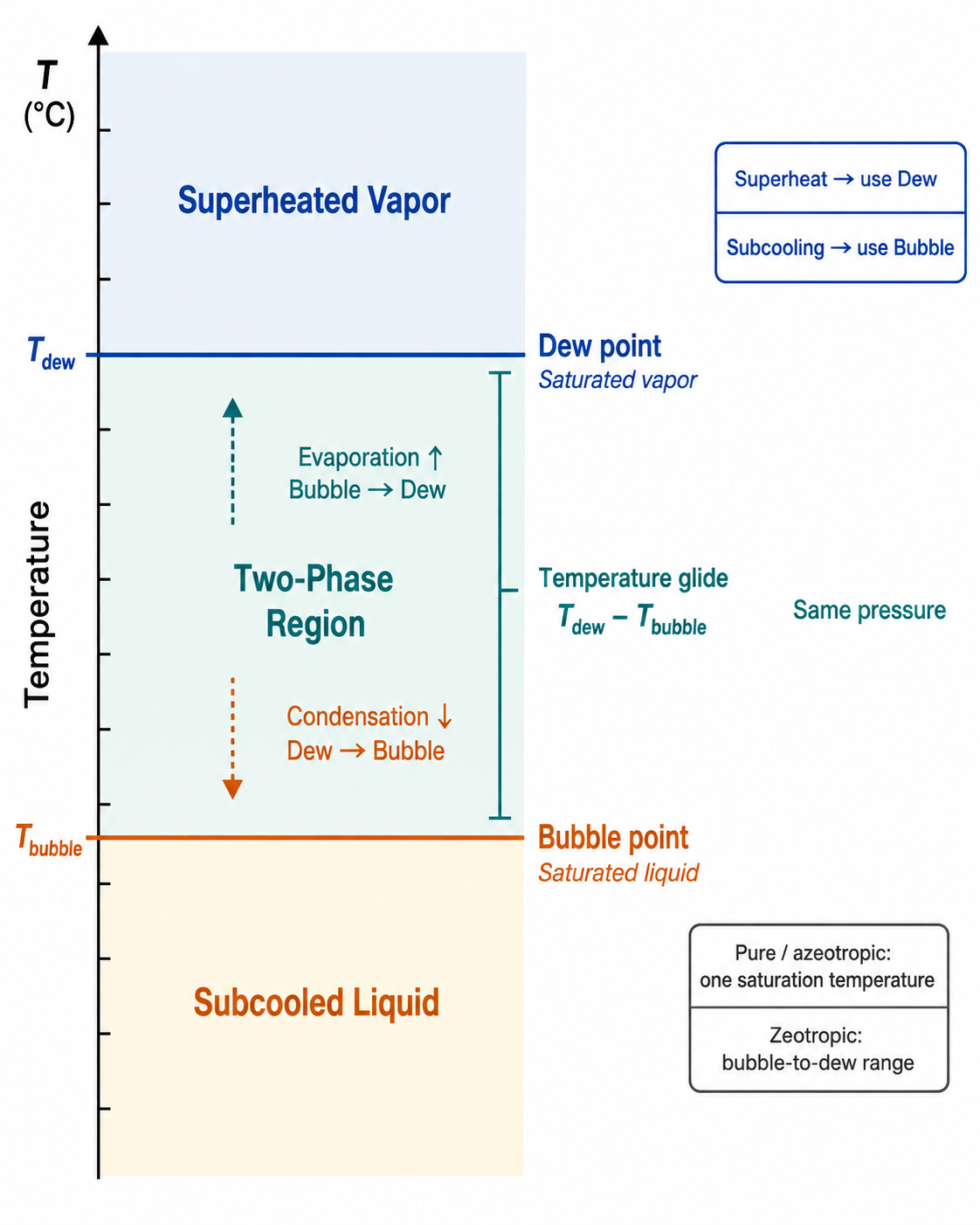
Figure 3.3.1 – Bubble point, dew point, and temperature glide of a zeotropic refrigerant blend at a fixed pressure.
AI-generated instructional figure: It may contain visual inaccuracies. Use the accompanying lesson text and cited authoritative sources to verify technical and regulatory details.
EPA 608 Exam Focus
What Students Must Remember
- Temperature glide applies to zeotropic refrigerant blends.
- Temperature glide = dew point − bubble point at the same pressure.
- Bubble point is the saturated-liquid boundary.
- Dew point is the saturated-vapor boundary.
- During evaporation:
- Phase change begins at bubble point.
- Phase change finishes at dew point.
- During condensation:
- Phase change begins at dew point.
- Phase change finishes at bubble point.
- For a zeotropic blend:
- Superheat → use dew point.
- Subcooling → use bubble point.
- A near-azeotropic blend has small glide but remains zeotropic.
- Not every 400-series blend has large glide.
- A leak can cause fractionation, but the effect is not identical for every leak.
- Zeotropic blends are normally withdrawn from the supply cylinder as liquid.
- Pressure-temperature values must match the correct refrigerant and pressure basis.
- Pressure alone is not sufficient to identify an unknown refrigerant.
Typical Exam Question Patterns
Students may be asked to:
- Define temperature glide.
- Identify bubble point as the liquid-side saturation value.
- Identify dew point as the vapor-side saturation value.
- Select the correct P-T chart column for superheat.
- Select the correct P-T chart column for subcooling.
- Determine the direction of temperature change through a zeotropic evaporator.
- Determine the direction of temperature change through a zeotropic condenser.
- Explain why charging a zeotropic blend as liquid helps preserve composition.
- Distinguish fractionation from temperature glide.
- Identify an overgeneralized statement about leaks or blend behavior.
High-Priority Comparison
| Exam Clue | Correct Concept |
|---|---|
| First vapor forms during heating | Bubble point |
| Saturated-liquid boundary | Bubble point |
| Last liquid evaporates | Dew point |
| Saturated-vapor boundary | Dew point |
| Dew minus bubble | Temperature glide |
| Superheat calculation | Dew-point reference |
| Subcooling calculation | Bubble-point reference |
| Bubble → Dew | Evaporation |
| Dew → Bubble | Condensation |
| Composition changes after preferential loss | Fractionation |
Common Mistakes and Confusing Points
Mistake 1: Reversing Bubble and Dew
Correct relationship:
Bubble = saturated liquid
Dew = saturated vapor
Mistake 2: Using Bubble Point for Superheat
Superheat concerns vapor.
Use the dew-point saturation temperature.
Mistake 3: Using Dew Point for Subcooling
Subcooling concerns liquid.
Use the bubble-point saturation temperature.
Mistake 4: Treating Glide as a Pressure Difference
Glide is a temperature difference at the same pressure.
Mistake 5: Assuming a Zeotropic Blend Boils at One Fixed Temperature
A zeotropic blend can change saturation temperature as it evaporates at approximately constant pressure.
Mistake 6: Assuming Every 400-Series Blend Has Large Glide
Some have very small glide.
Mistake 7: Assuming Small Glide Means the Refrigerant Is Azeotropic
Near-azeotropic is still zeotropic.
Mistake 8: Treating Fractionation and Glide as the Same Thing
Glide is a temperature range.
Fractionation is a composition change.
Mistake 9: Assuming Any Leak Automatically Requires Discarding the Entire Charge
The effect of a leak depends on the blend and leak conditions.
Follow manufacturer procedures rather than inventing a universal rule.
Mistake 10: Averaging Bubble and Dew for Every Service Calculation
For the calculations emphasized here:
- Dew → superheat.
- Bubble → subcooling.
Use an average only when a specific approved procedure requires it.
Concept-Check Questions
Question 1
What is temperature glide for a zeotropic refrigerant blend?
A. The difference between discharge pressure and suction pressure
B. The difference between dew-point and bubble-point temperatures at the same pressure
C. The amount of superheat measured at the compressor
D. The amount of refrigerant lost during a leak
Question 2
What does the bubble point represent for a zeotropic refrigerant blend?
A. The saturated-liquid boundary
B. The superheated-vapor boundary
C. The temperature at which all vapor has been superheated
D. The midpoint between suction and discharge pressure
Question 3
What does the dew point represent for a zeotropic refrigerant blend?
A. The subcooled-liquid temperature
B. The temperature at which the first vapor begins to form during heating
C. The saturated-vapor boundary
D. The average of all component boiling temperatures
Question 4
Which saturation reference should normally be used to calculate superheat for a zeotropic blend?
A. Bubble-point temperature
B. Dew-point temperature
C. The average of bubble and dew in every case
D. The outdoor-air temperature
Question 5
Which saturation reference should normally be used to calculate subcooling for a zeotropic blend?
A. Bubble-point temperature
B. Dew-point temperature
C. Compressor discharge temperature
D. The midpoint of the glide regardless of manufacturer instructions
Question 6
During evaporation of a typical zeotropic blend at approximately constant pressure, which sequence is correct?
A. Dew point → bubble point
B. Superheated vapor → subcooled liquid without a two-phase region
C. Bubble point → two-phase region → dew point
D. Bubble point → subcooling → dew point
Question 7
Which statement correctly distinguishes temperature glide from fractionation?
A. Glide is a composition change, while fractionation is a pressure difference.
B. Glide is the bubble-to-dew temperature range, while fractionation is a change in blend composition.
C. Both terms mean exactly the same thing.
D. Fractionation applies only to pure refrigerants.
Question 8
Which statement about a near-azeotropic 400-series refrigerant is correct?
A. It must have zero glide.
B. It becomes a 500-series refrigerant whenever bubble and dew temperatures are close.
C. Bubble and dew concepts never apply to it.
D. It is still a zeotropic blend, but its temperature glide is small.
Answers and detailed explanations will be provided in
3.10 - Answers and Explanations.md.
Section Summary
A zeotropic refrigerant blend can have two saturation temperatures at one pressure:
- Bubble point — saturated-liquid boundary.
- Dew point — saturated-vapor boundary.
The difference is temperature glide:
During evaporation:
Bubble point
→ two-phase region
→ dew point
During condensation:
Dew point
→ two-phase region
→ bubble point
For technician-level P-T chart use:
Superheat → Dew
Subcooling → Bubble
Temperature glide and fractionation are related blend concepts but are not the same:
- Glide describes a temperature range.
- Fractionation describes a composition change.
Zeotropic blends are normally withdrawn from a supply cylinder as liquid to help preserve blend composition. Leakage can alter composition, but the amount and significance of fractionation depend on the actual leak and blend conditions.
The next section develops how refrigerant identity is established using:
- Equipment nameplate.
- Cylinder label.
- Pressure-temperature relationship.
- Refrigerant analyzers.
- Contamination awareness.
See Section 3.4 - Refrigerant Identification.
References
Project Source
- Current EPA Section 608 teaching-material project outline, Module 3 — Refrigerants Blends and Lubricants, Section 3.3 learning scope and Figure 3.3.1 specification, reviewed August 7, 2026. The outline requires temperature glide, bubble point, dew point, P-T chart interpretation for blends, charging and leak implications, and avoidance of overgeneralization.
HVAC Licensing Reference
- Rex Miller and Mark R. Miller, HVAC Licensing Study Guide, 3rd ed., refrigerant review material. The study guide identifies temperature glide as the difference between dew-point and bubble-point temperatures at a given pressure and distinguishes azeotropic from zeotropic behavior.
Refrigerant Property Reference
- NCEES, PE Mechanical Reference Handbook, Version 2.0, 2025, Chapter 8 — Refrigeration. The ASHRAE-based refrigerant property tables identify separate bubble temperatures for liquid and dew temperatures for vapor for refrigerant blends such as R-410A.